| Previous Page | Up One Level |
Lecture Slides available: PDF PowerPoint
DBMS Implementation
Contents
Implementing a DBMS
A database management system handles the requests generated from the SQL interface, producing or modifying data in response to these requests. This involves a multilevel processing system.
-
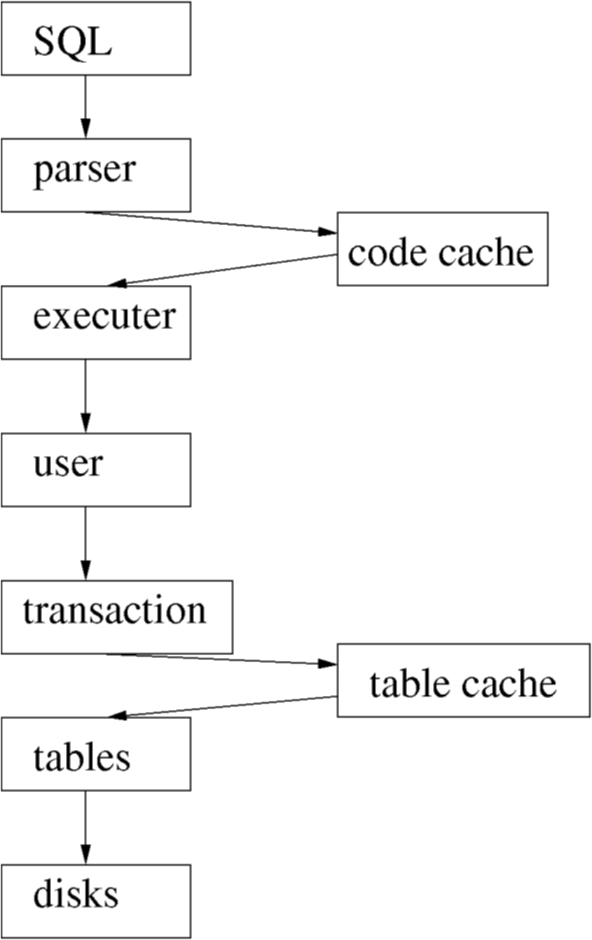
- Figure : DBMS Execution and Parsing
This level structure processes the SQL submitted by the user or application.
- Parser: The SQL must be parsed and tokenised. Syntax errors are reported
back to the user. Parsing can be time consuming, so good quality DBMS
implementations cache queries after they have been parsed so that
if the same query is submitted again the cached copy can be used instead.
To make the best use of this most systems use placeholders in queries, like:
SELECT empno FROM employee where surname = ?
The '?' character is prompted for when the query is executed, and can be supplied separately from the query by the API used to inject the SQL. The parameter is not part of the parsing process, and thus once this query is parsed once it need not be parsed again. - Executer: This takes the SQL tokens and basically translates it into relational algebra. Each relational algebra fragment is optimised, and the passed down the levels to be acted on.
- User: The concept of the user is required at this stage. This gives the query context, and also allows security to be implemented on a per-user basis.
- Transactions: The queries are executed in the transaction model. The same query from the same user can be executing multiple times in different transactions. Each transaction is quite separate.
- Tables : The idea of the table structure is controlled at a low level. Much security is based on the concept of tables, and the schema itself is stored in tables, as well as being a set of tables itself.
- Table cache: Disks are slow, yet a disk is the best way of storing long-term data. Memory is much faster, so it makes sense to keep as much table information as possible in memory. The disk remains synchronised to memory as part of the transaction control system.
- Disks : Underlying almost all database systems is the disk storage system. This provides storage for the DBMS system tables, user information, schema definitions, and the user data itself. It also provides the means for transaction logging.
The 'user' context is handled in a number of different ways, depending on the database system being used. The following diagram gives you an idea of the approach followed by two different systems, Oracle and MySQL.
-
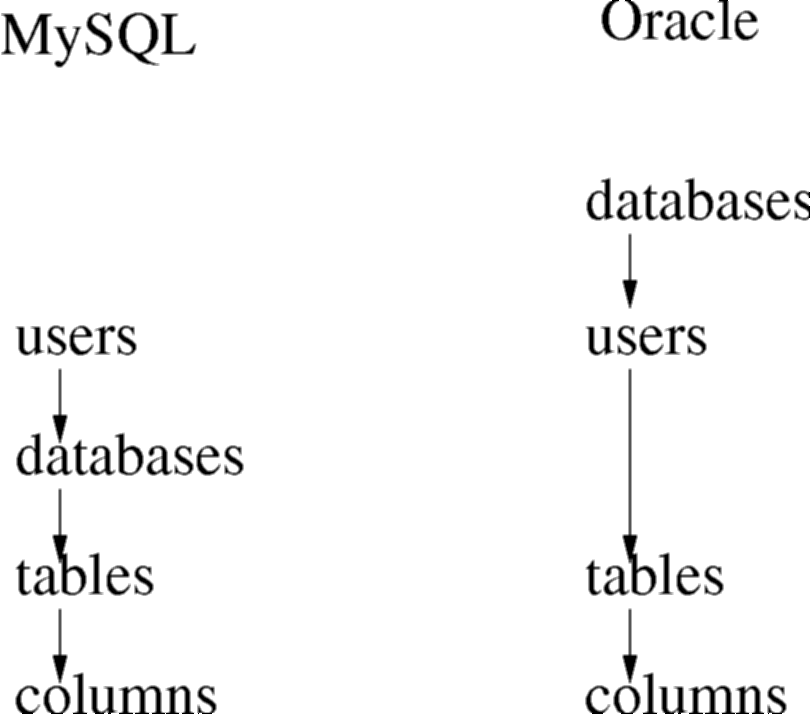
- Figure : Users and Tablespaces
All users in a system have login names and passwords. In Oracle, during the connection phase, a database name must be provided. This allows one Oracle DBMS to run multiple databases, each of which is effectively isolated from each other.
Once a user is connected using a username and password, MySQL places the user in a particular tablespace in the database. The name of the tablespace is independent of the same. In Oracle, tablespaces and usernames are synonymous, and thus you should really be thinking of different usernames for databases that serve different purposes. In MySQL the philosophy is more like a username is a person, and that person may want to do a variety of tasks.
Once in a tablespace, a number of tables are visible, and in each table columns are visible.
In both approaches, tables in other tablespaces can be accessed. MySQL effectively sees a tablespace and a database being the same concept, but in Oracle the two ideas are kept slightly more separate. However, the syntax remains the same. Just as you can access column owner of table CAR, if it is in your own tablespace, by saying
SELECT car.owner FROM car;You can access table CAR in another tablespace (lets call it vehicles) by saying:
SELECT vehicles.car.owner FROM vehicles.car;
The appearance of this structure is similar in concept to the idea of file directories. In a database the directories are limited to "folder.table.column", although "folder" could be a username, a tablename, or a database, depending on the philosophy of the database management system. Even then, the concept is largely similar.
Disk and Memory
The tradeoff between the DBMS using Disk or using main memory should be understood...
| Issue | Main Memory VS Disk |
|---|---|
| Speed | Main memory is at least 1000 times faster than Disk |
| Storage Space | Disk can hold hundreds of times more information than memory for the same cost |
| Persistence | When the power is switched off, Disk keeps the data, main memory forgets everything |
| Access Time | Main memory starts sending data in nanoseconds, while disk takes milliseconds |
| Block Size | Main memory can be accessed 1 word at a time, Disk 1 block at a time |
The DBMS runs in main memory, and the processor can only access data which is currently in main memory. The handling of the differences between disk and main memory effectively is at the heart of a good quality DBMS.
Disk Arrangements
Efficient processing of the DBMS requests requires efficient handling of disk storage. The important aspects of this include:
- Index handling
- Transaction Log management
- Parallel Disk Requests
- Data prediction
With indexing, we are concerned with finding the data we actually want quickly and efficiently, without having to request and read more disk blocks than absolutely necessary. There are many approaches to this, but two of the more important ones are hash tables and binary trees.
When handling transaction logs, the discussion we have had so far has been on the theory of these techniques. In practice, the separation of data and log is much more blurred. We will look at one technique for implementing transaction logging, known as shadow paging.
Finally, the underlying desire of a good DBMS is to never be in a position where no further work can be done until the disk gives us some data. Instead, by using prediction, prefetching, and parallel disk operations, it is hoped that CPU time becomes the limiting factor.
Hash tables
A Hash table is one of the simplest index structures which a database can implement. The major components of a hash index is the "hash function" and the "buckets". Effectively the DBMS constructs an index for every table you create that has a PRIMARY KEY attribute, like:
CREATE TABLE test (
  id   INTEGER PRIMARY KEY
 ,name varchar(100)
);
In table test, we have decided to store 4 rows...
insert into test values (1,'Gordon');
insert into test values (2,'Jim');
insert into test values (4,'Andrew');
insert into test values (3,'John');
The algorithm splits the places which the rows are to be stored into areas. These areas are called buckets. If a row's primary key matches the requirements to be stored in that bucket, then that is where it will be stored. The algorithm to decide which bucket to use is called the hash function. For our example we will have a nice simple hash function, where the bucket number equals the primary key. When the index is created we have to also decide how many buckets there are. In this example we have decided on 4.
-
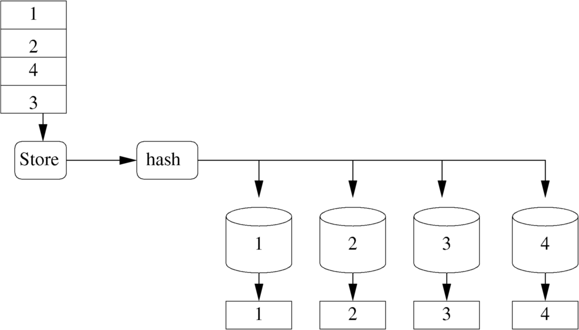
- Figure : Hash Table with no collisions
Now we can find id 3 quickly and easily by visiting bucket 3 and looking into it. But now the buckets are full. To add more values we will have to reuse buckets. We need a better hash function based on mod 4. Now bucket 1 holds ids (1,5,9...), bucket 2 holds (2,6,10...), etc.
-
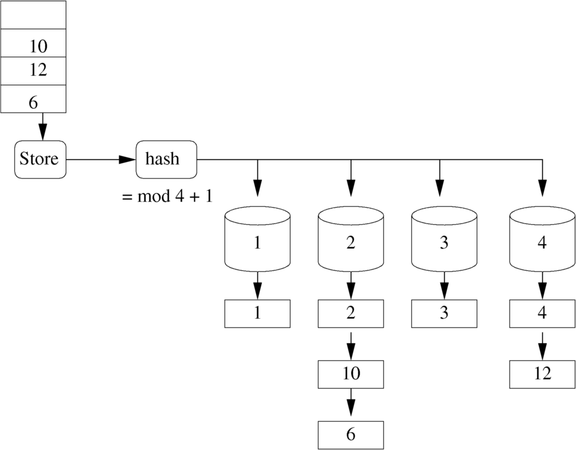
- Figure : Hash Table with collisions
We have had to put more than 1 row in some of the buckets. This is called a hash collision. The more collisions we have the longer the collision chain and the slower the system will get. For instance, finding id 6 means visiting bucket 2, and then finding id 2, then 10, and then finally 6.
In DBMS systems we can usually ask for a hash index for a table, and also say how many buckets we thing we will need. This approach is good when we know how many rows there is likely to be. Most systems will handle the hash table for you, adding more buckets over time if you have made a mistake. It remains a popular indexing technique.
Binary Tree
Binary trees is the latest approach to providing indexes. It is much cleverer than hash tables, and attempts to solve the problem of not knowing how many buckets you might need, and that some collision chains might be much longer than others. It attempts to create indexes such that all rows can be found in a similar number of steps through the storage blocks.
The state of the art in binary tree technology is called B+ Trees. With B+ tree, the order of the original data is maintained in its creation order. This allows multiple B+ tree indices to be kept for the same set of data records.
- the lowest level in the index has one entry for each data record.
- the index is created dynamically as data is added to the file.
- as data is added the index is expanded such that each record requires the same number of index levels to reach it (thus the tree stays `balanced').
- the records can be accessed via an index or sequentially.
Each index node in a B+ Tree can hold a certain number of keys. The number of keys is often referred to as the `order'. Unfortunately, `Order 2' and `Order 1' are frequently confused in the database literature. For the purposes of our coursework and exam, `Order 2' means that there can be a maximum of 2 keys per index node. In this module, we only ever consider order 2 B+ trees.
B+ Tree Example
-
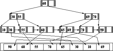
- Figure : Completed B+ Tree
-
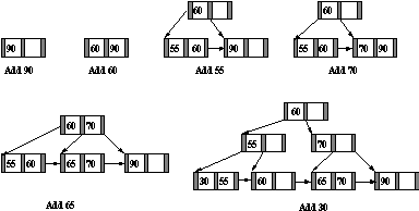
- Figure : Initial Stages of B+ Tree
-
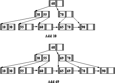
- Figure : Final Stages of B+ Tree
Index Structure and Access
- The top level of an index is usually held in memory. It is read once from disk at the start of queries.
- Each index entry points to either another level of the index, a data record, or a block of data records.
- The top level of the index is searched to find the range within which the desired record lies.
- The appropriate part of the next level is read into memory from disc and searched.
- This continues until the required data is found.
- The use of indices reduce the amount of file which has to be searched.
Costing Index and File Access
- The major cost of accessing an index is associated with reading in each of the intermediate levels of the index from a disk (milliseconds).
- Searching the index once it is in memory is comparatively inexpensive (microseconds).
- The major cost of accessing data records involves waiting for the media to recover the required blocks (milliseconds).
- Some indexes mix the index blocks with the data blocks, which means that disk accesses can be saved because the final level of the index is read into memory with the associated data records.
Use of Indexes
- A DBMS may use different file organisations for its own purposes.
- A DBMS user is generally given little choice of file type.
- A B+ Tree is likely to be used wherever an index is needed.
- Indexes are generated:
- (Probably) for fields specified with `PRIMARY KEY' or `UNIQUE' constraints in a CREATE TABLE statement.
- For fields specified in SQL statements such as CREATE [UNIQUE] INDEX indexname ON tablename (col [,col]...);
- Primary Indexes have unique keys.
- Secondary Indexes may have duplicates.
- An index on a column which is used in an SQL `WHERE' predicate is likely to speed up an enquiry.
- this is particularly so when `=' is involved (equijoin)
- no improvement will occur with `IS [NOT] NULL' statements
- an index is best used on a column with widely varying data.
- indexing a column of Y/N values might slow down enquiries.
- an index on telephone numbers might be very good but an index on area code might be a poor performer.
- Multicolumn index can be used, and the column which has the biggest range of values or is the most frequently accessed should be listed first.
- Avoid indexing small relations, frequently updated columns, or those with long strings.
- There may be several indexes on each table. Note that partial indexing normally supports only one index per table.
- Reading or updating a particular record should be fast.
- Inserting records should be reasonably fast. However, each index has to be updated too, so increasing the indexes makes this slower.
- Deletion may be slow.
- particularly when indexes have to be updated.
- deletion may be fast if records are simply flagged as `deleted'.
Shadow Paging
The ideas proposed for implementing transactions are prefectly workable, but such an approach would not likely be implemented in a modern system. Instead a disk block transaction technique would more likely be used. This saves much messing around with little pieces of information, while maintaining disk order and disk clustering.
Disk clustering is when all the data which a query would want has been stored close together on the disk. In this way when a query is executed the DBMS can simple "scoop" up a few tracks from the disk and have all the data it needs to complete the query. Without clustering, the disk may have to move over the whole disk surface looking for bits of the query data, and this could be hundreds of times slower than being able to get it all at once. Most DBMS systems perform clustering techniques, either user-directed or automatically.
With shadow paging, transaction logs do not hold the attributes being changed but a copy of the whole disk block holding the data being changed. This sounds expensive, but actually is highly efficient. When a transaction begins, any changes to disk follow the following procedure:
- If the disk block to be changed has been copied to the log already, jump to 3.
- Copy the disk block to the transaction log.
- Write the change to the original disk block.
On a commit the copy of the disk block in the log can be erased. On an abort all the blocks in the log are copied back to their old locations. As disk access is based on disk blocks, this process is fast and simple. Most DBMS systems will use a transaction mechanism based on shadow paging.
Disk Parallelism
When you look at an Oracle database implementation, you do not see one file but several...
ls -sh /u02/oradata/grussell/

2.8M control01.ctl
2.8M control02.ctl
2.8M control03.ctl
 11M redo01.log
 11M redo02.log
 11M redo03.log
351M sysaux01.dbf
451M system01.dbf
3.1M temp01.dbf
 61M undotbs01.dbf
 38M users01.dbf
Each of these files has a separate function in Oracle, and requests can be fired to each of them in parallel. The transaction logs are called redo logs. The activesql interface is stored completely in users01. In my case all the files are in a single directory on a single disk, but each of the files could be on a different disk, meaning that the seek times for each file could be in parallel.
Caching of the files is also going on behind the scenes. For instance, the activesql tables only take up 38MB, and thus can live happly in memory. When queries come in the cache is accessed first, and if there is a need to go to disk then not only is the data requested read, but frequently data nearby that block is also read. This is called prefetching, and is based on the idea that if I need to go to disk for something, I might as well get more than I need. If it turns out that the other stuff is not needed, then not much time or resource was wasted, but if the other stuff is needed in the near future, the DBMS gains a huge performance hit. Algorithms help to steer the preloading strategy to its best possible probability of loading useful data.
Lastly, the maximum performance of a database is achieved only when there are many queries which can run in parallel. In this case data loaded for one query may satisfy a different query. The speed of running 1 query on an empty machine may not be significantly different from running 100 similar queries on the machine.
| Previous Page | Up One Level |
| ||||
| ||||
|